Overview
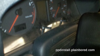
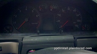
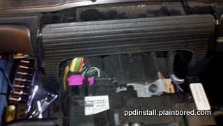
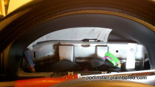
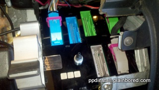
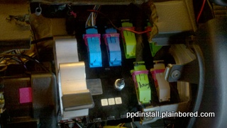
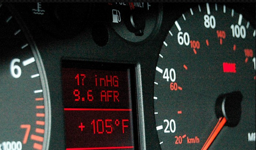
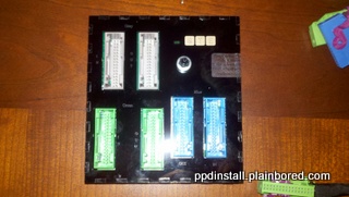
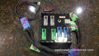
The PPD unit allows you to fully interface your gauge solution into the DIS of your existing cluster. Moreover, it also allows for you to do logging automatically. It's extremely useful and a great addition to your Audi.
Disclaimer
No warranties expressed or implied. This information is for educational purposes only. I am not liable or responsible for anything you do. By reading this article, you are in agreement with the aforementioned terms.
Application
This article is specifically written for the facelift style (99.5 to 01.5) Audi A4 1.8T Quattro with a manual transmission. All photos are from a 2001 Audi A4 1.8T Quattro with a manual transmission. Granted these instructions can be used for other models as well because the idea is very similar but keep in mind that it is directed specifically at the A4.
Copyright
Replication of any portion of this site including (but not limited to) it's HTML, Images, etc. is strictly forbidden without the expressed, written consent of its author.
Installation Time
1 Hour (with taking photos)
Cost
- $399.99 - STE PPD Unit - Source
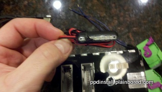
- $19.99 - Micro Shift LED add on
Supplies Needed
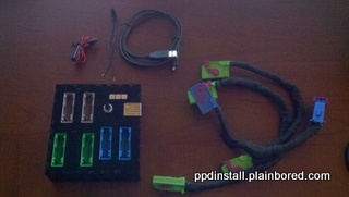
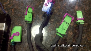
- PPD Unit & wiring harness
- 4' 1/8" vacuum line
- Something to lay on top of the steering column to protect it like a small rag or a piece of cloth
Tools Needed
- Torx T20 socket
- VAG-COM / VCDS / VAD Mobile
- 10mm socket
- 8mm socket
- 1/4" (or 3/8") ratchet
- 1/4" (or 3/8") extension
Information Source(s)
Steps
Step 1 - Download & install PPD Connect software
The PPD Connect software is available after purchase of PPD unit.
- Extract the attached zip file to a folder on your computer
- Connect the provided USB cable to PPD
- The driver file for PPD is located in the Driver folder that you just extracted
- Direct the windows driver installation to the location of this folder and complete the driver installation
- Launch PPD Connect -> connect to the new COM PORT.
- Select your cluster type (my 01 A4 is a D12). If you don't know the cluster type, no big deal. Using a VAG-COM or alike you will be able to see that during the adaptation step.
Step 2 - Run adaptation on the cluster
This will set up your cluster to be able to interface with the PPD
- Connect VAG-COM cable to diagnostic port
- Click Select under Select Control Module
- Click 17-Instruments under the Common tab
- Click Adaptation
- Read channel 062
- Enter "15" into the value (for A4/S4/RS4/A6/RS6) or "7" (for the TT)
- Click Test
- Click Save
Step 3 - Disconnect battery or remove instrument fuse
This will avoid any damage to either the PPD unit or your cluster during installation.
| Battery cover: |  |
| Battery location (disconnecting the battery is only necessary if you are not removing the fuse for the instrument panel): | 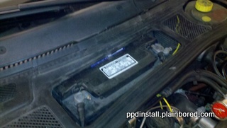 |
| Fuse panel cover (the fuse is in position 10 in my A4): | 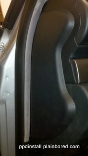 |
Step 4 - Remove cluster
There isn't much room between the cluster & the dash once you start to pull it out so you will need to disconnect the wires by reaching around it.
- Remove cover on top of steering console
- Pull back flexable plastic to expose two Torx bolts under the cluster
- Remove two torx bolts
- Place rag or alike on the top of the steering column to protect it
- Pull cluster forward and reach behind to unclip the 3 harnesses (you need to flip the latch on them to pull them apart)
Step 5 - Remove lower bolster
- Remove plastic covers that hide 2 bolts
- Unbolt 4 bolts holding the lower bolster up (one is on the left behind the fuse panel cover & another is below the bolster on the right side)
- Lower the bolster enough to see the OBDII & interior light connectors
- Disconnect OBDII connector
- Disconnect lower bolster lamp connector
| Left plastic cover: | 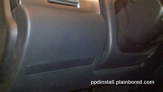 |
| Right plastic cover: | 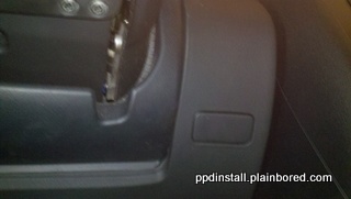 |
| Fuse panel cover covering left bolt: |  |
| OBDII connector: | 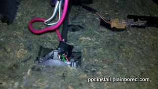 |
| Lamp connector: | 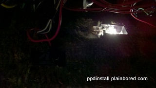 |
Step 6 - Run boost line for MAP sensor
In my car I already had the boost line run for my Podi gauge so what you will want to do is to run the line through either your ECU box or use one of the existing areas to put a hose through. A4Mods.com has a nice write up on it, here.
| Vacuum line: | 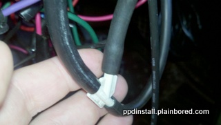 |
Step 7 - Hook wires to back of cluster
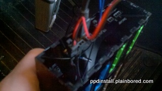
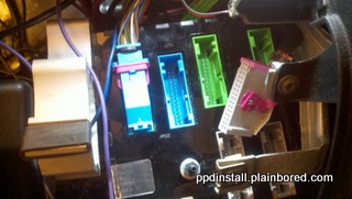
Hooking the new PPD wires up to the back cluster makes it easier to connect the PPD unit once inside the dash.
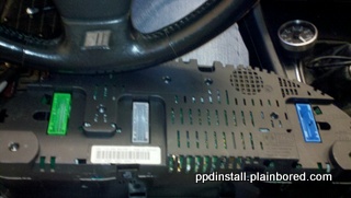
| Blue connector: | 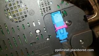 |
| Green & "Gray" connectors: | 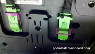 |
| Put connectors into position: | 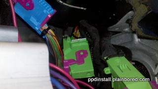 |
Step 8 - Position PPD under dash
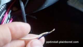
Hook up any additional inputs (ie. wideband O2, etc.). For the purposes of this installation, I hooked the output of my Zeitronix wideband (white wire) to the WB input of the PPD. I'd recommend you solder it because you will need a solid connection or you will get poor sensor readings. Also ensure that your wideband provides 0-5v or you will damage your PPD.
Step 9 - Test & put it back together
Make sure your connections are all solid and then you can put the fuse back in for the cluster to test. If all is well, put everything back together.
| Check the display metrics: | 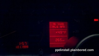 |
Step 10 - Enjoy!
You can use the stalk on the right side to control which display you want to use. It's also how you switch boost profiles if you have the boost controller option.
| Another neat feature of the PPD: | 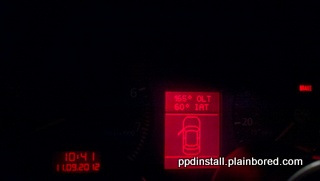 |
Contact Us
If you have any questions or concerns, please feel free to contact us at ppdInstall@plainbored.com
If you really like this write up and want to donate $5 to help with server expenses, please click below.
Good luck!
